Demystifying Bézier Drawing Tools
The engineering of Bézier drawing tools in programs such as Adobe Illustrator, Macromedia FreeHand, and QuarkXPress 4 certainly opens a world of opportunity and creativity for many users. But, if you’re unfamiliar with the use of these far-from-simple tools, they do you little good. In this article, we’ll use the Bézier tools included in QuarkXPress 4.0 to show you the power of the Bézier drawing tools, and how to control and manipulate them with a high degree of flexibility.
What Exactly is a Bézier?
The term bézier (bezz-ee-aye) drawing stems from the name of mathematician Pierre Bézier, who formulated principles on which vector objects are based. In simple terms, his theory states that all shapes are composed of segments and points. Segments may be either curved or straight while their condition and shape are controlled by properties of the points that join them. A collection of two or more points joined by line or curve segments is referred to as a path. Two or more paths combined to form a broken or non-continuous series of segments and points are called a compound path. And that’s your history lesson for today. Once a Bézier path exists in digital form on the page, it can be assigned specific properties such as line width, patterns (dash and stripe), arrowheads, and color. Paths can also be open or closed, a condition that’s determined by whether the endpoints of the path are unjoined (open) or whether they’re joined to form a continuous loop (closed). If a path is closed, it can also be filled with color, or converted from a shape box to a picture or text box. Open paths can be converted to text paths.
Anatomy of a Bézier Path
Bézier drawing in QuarkXPress follows Pierre’s theory with the same accuracy enjoyed by most graphic applications. QuarkXPress now includes the Freehand Line, Bézier Line, Bézier Picture Box, Bézier Text Box, and Bézier Text Path tools for creating various open and closed paths. But, before you grapple too hard with using these tools, it may help to know a bit about the on-screen information provided by QuarkXPress to reflect the point and segment types you’re working with. Again, remember that these rules apply equally to FreeHand, Illustrator, or most any other application that uses the Bézier tools.
As mentioned earlier, path segments can be either straight or curved. Straight segments are simply joined end to end, while curved segments are more involved. The path followed by a curved segment is controlled by the properties of its adjoining points, which can be set to either smooth or symmetrical.
Corner points: These are points that enable the shape of segments on either side to be unaffected by each other. In other words, the straight or curved segments can be shaped to allow the path to abruptly change direction where the point joins them, as shown in Figure A. For this reason, the corner point is perhaps the easiest to work with.
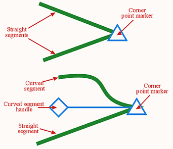
Figure A
Corner points enable the shape of segments on either side to be unaffected by each other.
Smooth points: As the name suggests, smooth points force the direction or angle of curved segments on either side to align, creating a smooth transition between the two endpoints, as shown in Figure B. Smooth point handles can be set to unequal distances from the point they control. This will apply only where a smooth point joins two curved segments. While a smooth point is in use, the point and both handles will be in alignment.
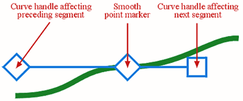
Figure B
Smooth points create a smooth transition between two endpoints.
Symmetrical points: These types of points force the curved segments on either side to be equal in slope or angle, as shown in Figure C. Unlike smooth points, symmetrical point handles can only be positioned equal distances from the points they control.
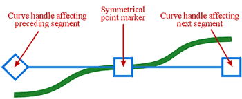
Figure C
Symmetrical points force the curved segments on either side to be equal in slope or angle.
Each smooth and symmetrical point features two curve handles. One handle controls the shape of the preceding segment, while the other controls the shape of the segment to follow. Curved segment endpoints-the points at the beginning and ends of each path-contain only one curve handle each to control the respective segment.
In an effort to enable you to distinguish which point is which, QuarkXPress displays each of the points and their associated handles in different ways. A corner point takes the shape of a triangle, a symmetrical point is square-shaped, and a smooth point takes the shape of a rotated square, or diamond.
Defining Points and Segments While Drawing
Any of the Bézier tools in QuarkXPress can be used to create a new Bézier path. But creating an accurately drawn path certainly takes a bit of practice. The mouse action involved in the creation of each point on your path plays a key role in the shape and properties associated with the points and segments it contains. A single click on your page creates a point position, while a second click creates another point with a straight segment between them. But a click-drag action with your mouse automatically creates a curved segment–and this is where the tricky part comes, as you can see in Figure D.
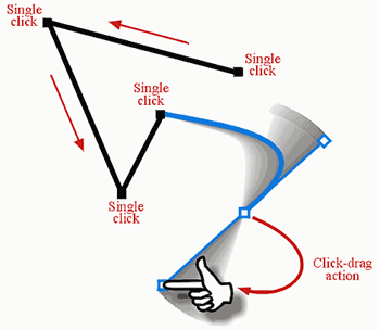
Figure D
When using the Bézier tools, different mouse actions create points and segments with varied shapes and properties.
As you click-drag to create a new point, several things occur in the background. First, the point at which you first clicked with the mouse defines the new point’s position, and now as you continue to drag, you’re no longer holding the actual point. Instead, you’re now dragging a curve segment handle that can be rotated 360 degrees around the new point position. By releasing the mouse button, you define the curve handle’s position, in turn affecting the shape of the curve segment you just created–and the next one you’re about to create. The process is ongoing until you’ve completed drawing your path. Choosing a different tool from the main toolbox, such as the Item tool (ICON), ends Bézier drawing sessions. Practice makes perfect and Bézier tools are no exception to this rule. While drawing using Bézier tools, you can also specify a specific point type (other than the default) by holding down the modifier keys that are listed in Table A, while defining each point’s position.

Table A
Use these modifier keys to specify a specific point.
Tip
- : Holding down [shift] as a modifier key, while defining a new point, will constrain the preceding segment angle to 90-degree increments. Holding down [shift], while click-dragging to define a new curve segment’s point, will constrain rotation of its curve handles to 45-degree increments.
Selecting and Editing Paths
Whether you’ve created your path from scratch using Bézier drawing tools or you’ve converted a box, shape, or text to a path, knowing how the points and line shapes can be changed or transformed is another critical area. Once you’ve created your path, editing the existing points or segments can be a complex process if you’re unfamiliar (or even if you are familiar) with commands for manipulation of the various components. To edit a path, you must use either the Item tool or the Content tool while an open or closed path is selected.
Tip
- : To reposition the entire path while it’s being created, hold down the [command] key and drag the path.
Both points and segments can be repositioned to any point on or off your layout page simply by dragging (or using the nudge keys), while the shape of curve segments can be altered by dragging their curve handles. To make the editing process even more important, straight segments can quickly be converted to curves or vice versa. Plus, the conditions of points can be interchanged between corner, smooth, and symmetrical states. Common commands for this type of editing can be found in a number of places. To find them, select Point/Segment Type from the Item menu, which only becomes available while a point or segment is selected.
But perhaps the most crucial companion to have around when editing points is the Measurements palette (press [F9]). The Measurements palette, as shown in Figure E, provides quick access to nearly all properties associated with points and segments, including fields for entering exact point or handle page positions, and buttons to set the condition of points and/or segments. The palette itself has been organized into two distinct areas.

Figure E
The Measurements palette provides quick access to nearly all properties associated with points and segments.
The left side of the palette includes the following controls:
- X and Y: These two fields display the current vertical and horizontal upper-left page position (relative to your ruler origin) of an invisible bounding box surrounding your selected path. To move the path, simply type in a new value followed by the [enter] key.
- W and H: These two options set the overall width and height dimensions of your selected path. To change the scale of your path, type in a new value followed by the [enter] key.
- Angle: This option enables you to perform a rotation of your selected path by entering a degree value followed by the [enter] key. Positive values rotate the path counterclockwise, while negative values rotate the path clockwise.
The right half of the palette is dedicated to points. The controls are as follows:
- XP and YP: These abbreviations represent the vertical and horizontal page position of the selected point (relative to your ruler origin). For precision positioning, type in a new value followed by the [enter] key.
- Curve Handle Angle: The boxes labeled with angle symbols represent the angle of the curve handles. The left angle box controls the curve handle affecting the preceding segment, while the right angle box controls the curve handle for the segment to follow.
- Curve Handle Position: The two boxes below the point angle boxes enable you to specify the curve handle distance from the point they protrude from. Changing the curve handle positions changes the shape of curve segments.
Between these path and point options are five buttons that enable you to change the condition of points or segments. On the top row, three buttons enable you to change the selected point(s) to symmetrical, smooth, and corner points, respectively. Below these, two buttons enable you to change a selected segment from (or to) a curved or straight segment.
When you draw a path using any of the Bézier drawing tools, the result is always an open path, meaning the first and last points remain unjoined. To join these points and close the path so that it can be filled with an image, text, or color, use the Item tool to select the path, hold down the [option] key, and choose Item>Shape>Bézier Box (fourth symbol from the bottom). If the points are on top of each other (or at least close together), the endpoints will become joined automatically.
Point and Segment Shortcuts
Many more options for editing segments and points are available by holding down modifier keys during your path or segment-editing process. Table B lists these keys and their functions, as well as other shortcuts used to select, alter, and transform points and segments.
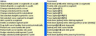
Table B
Using modifier keys when editing segments and points allows you to access many more options.
Conclusion
Bézier paths give you exacting measures and a high degree of control and flexibility unafforded to you by other drawing tools. And combining the background information here with a little practical experience on your part should get you started on the road to creativity and control.

Copyright © 2000, Element K Content LLC. All rights reserved. Reproduction in whole or in part in any form or medium without express written permission of Element K Content LLC is prohibited. Element K is a service mark of Element K LLC


