

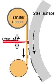
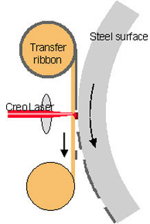
DICO™ Imaging Process: The imaging method of the DICO process is based on a widely used thermal transfer technology. The DICOweb transfer technology uses a ribbon to image a surface. The width of this ribbon is close to that of a video tape and, similar to a video tape, the ribbon is housed in a cartridge. The ribbon consists of a thin polymer substrate and a transfer layer. The transfer layer holds the material that is transferred to the printing surface pixel by pixel using a laser beam. The transferred pixels form the ink-accepting areas on the printing surface.
DICO™ Imaging Process
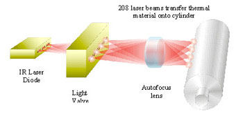
The DICO process uses a Creo SQUAREspot™ thermal exposure head, which provides the fastest and most precise thermal imaging capability available. SQUAREspot technology, which is shown schematically below, uses a proprietary light-valve technology to individually modulate over 200 precise beams of laser light. This is combined with a sophisticated autofocus system and built-in self-calibration. Outstanding optical resolution is achieved, allowing crisp 3200 dpi dots. Creo SQUAREspot™ imaging technology has a well-established record of reliability and performance, proven daily in over 1500 Creo CtP devices installed worldwide.
The high-power output of the Creo exposure head enables high-speed imaging, allowing the DICOweb to achieve fast make-ready times. The SQUAREspot technology creates an exceptionally precise, high-resolution image on the printing surface, al-lowing the DICOweb to print the most demanding jobs and achieve outstanding print quality, including the capability to print with high-resolution and stochastic (FM) screening.
The Creo SQUAREspot head and the DICO-process ribbon material form an ideal combination:
The outstanding precision and high-power density of SQUAREspot thermal imaging technology, together with the binary nature of the DICO process transfer ribbon, cre-ate a stable and predictable exposure process. Together they allow the highest-quality offset printing to be achieved without the need for traditional printing plates.
System Architecture Overview
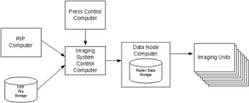
Raster data is input to the Imaging System Control Computer from 1-bit TIFF files or via direct connection to the RIP Computer. The raster data is downloaded to the Data Node Computer, which is used to buffer image data in preparation for imaging. The Data Node Computer may hold a number of jobs, any of which may be imaged at the push of a button on the Press Control Computer. Each imaging unit consists of a Creo SQUAREspot thermal exposure head, plus associated control electronics. High-speed electronics in the Data Node Computer allow all separations of a job to be im-aged simultaneously. Each printing unit on the press contains two complete imaging units (upper and lower).
Technical Data
Data input: TIFF (1 bit) downloading function or direct connection to RIP and workflow systems
Data rate for download to Data Node Computer: 10 Mbyte/s Press Image Storage: 9 Gbyte per imaging unit (12 Jobs, based on 630 mm cylinder circumference)
Exposure head output power: 18 W, liquid cooling
Resolution: 3200 dpi and 1600 dpi
Write-laser wavelength: 820 nm to 840 nm
Number of channels: 208
Simultaneous imaging on up to 12 imaging units (6 printing units) per system (total data rate > 100 Mbytes/second)
Easily replaceable cartridges
Number of tracks per cartridge: 6 tracks
Images per track (for 630 mm cylinder circumference): 4 Recording speed: appr. 0,5 min per A4 page
This article was last modified on June 30, 2023
This article was first published on May 16, 2000
Commenting is easier and faster when you're logged in!

Recommended for you

New Versions of FiFi, Fido, and Split & Folio Now Available
Managing Editor Inc. (MEI), an Adobe premier development partner and a leading p...

Get Many Images From One Original Photo
Did you realize that big photos have small photos hidden in the details—a collar...

Tip of the Week: Numbering Above a List, Part 2
Another way to set list numbers above the rest of the paragraph text, that works...